Measured Flow
These are documents / message made within the NBM Working group for common use.
The work is limited by what should be exchanged between Nordic TSOs.
This is our working documents which we have agreed on.It is the raw documentation which we have discussed within NBM working group, and will probably be published in a different layout in near future.
Introduction
Measured flow is sum of all measured flow on an interconnector between bidding zones. It consists of Real time values(PT10S) and Historical values which can be more accurate(corrected) than real time values.
The Nordic TSOs provide provide roviding FiftyOne, a monitoring system for System Operators with different Flow-values.
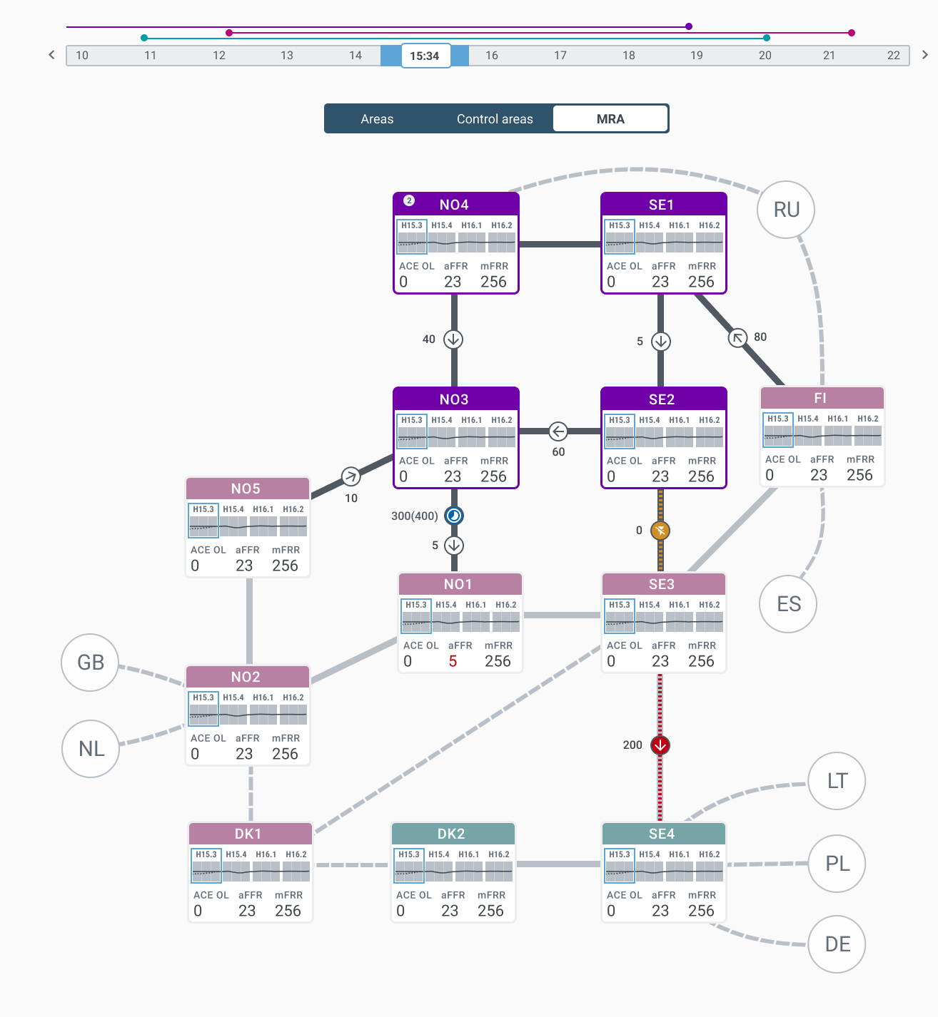
FiftyOne will present all Flows in their GUI as shown in figure below, in addition all or single part of these flows will be used for other purposes as shown in use case below.
In this context we focus only on measured flow which is used
Business Process
Operator wish to see values for planned and measured flow on the corridor in the map. All other values will be shown in a graph. Operator does not need detail card on corridors, just a detail window with graph.
Measured flow
Measured Flow consists of the following data exchanges:
-
Measured Real-time values ( what about measured versus estimated?)
-
Measured Historical values is made to meet the requirements to obtain historical data (F-BR-3, see description).
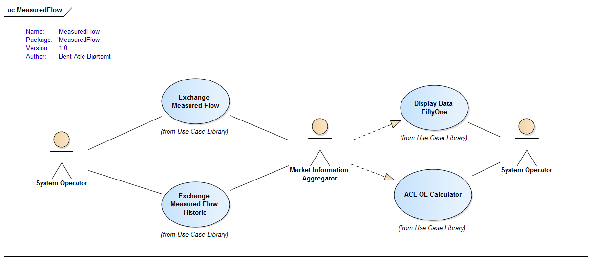
Use cases for measured flow:
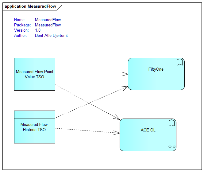
Definition of ACE Open Loop (ACE OL)
ACE Open Loop (ACE OL)
ACE OL: ACE Open Loop (ACE OL) is the real-time imbalance of an area in the power system without automatic Frequency Restoration Reserve(aFRR) and manual Frequency Restoration Reserves(mFRR). ACE OL is the imbalance before any operator balancing actions. The imbalance prognosis is the prognosis of ACE OL.
ACE : Area Control Error (ACE) is the real-time difference between scheduled and actual electrical flow in and out of an area in the power grid, taking frequency bias into account. ACE, also named ACE Closed Loop, is the remaining imbalance after all operator balancing actions.
General calculation methodology for ACE OL:
ACE OL = Measured flow - Planned flow - Total regulations
-
The Measured flow is the sum of the measured flow on all interconnectors to an area.
-
The measured flow on one interconnector is the sum of the measured flow on all lines between two bidding zones measured in an agreed reference point.
-
Reference point should be defined as one, or the aggregation of more, physical points in the system. For the connection between DK2-SE4 one physical point is in Sweden and one in Denmark. Points should always be defined in a location where there are measurements, not "in the middle of" , "at the seabed" or similar.
-
-
Planned flow = Power Plan Trade + Other agreed flow.
-
Power plan trade is the ramped power plan resulting from the Day ahead and intraday market in an agreed reference point.
-
Other agreed flow includes all other scheduled flow between bidding zones that is agreed before the mFRR balancing time frame.
-
Loop transit product 1…n
-
Agreed Supportive Power product 1..n
-
Planned period shift adjustments ("Produksjonsglatting").
-
-
-
Total regulations = K*∆f + aFRR + mFRR + other balancing activation – exchanged regulations to other synchronous areas.
-
K*∆f is the frequency response of each area.
-
K[MW/Hz] = planned FCR-N*10 * self-regulation.
-
Planned FCR-N in MW.
-
Self regulation is the response from frequency dependent loads. This could be added to the FCR-N volume to obtain the total K-factor. It should be set in a coordinated way for all TSOs.
-
-
∆f is the difference between the target frequency for FCR and the measured frequency.
-
Target frequency for the FCR activation is always 50,00Hz, even if the TSO target frequency can sometimes deviate in relation to time error correction.
-
Measured frequency is the instantaneous frequency value measured per LFC area.
-
-
-
aFRR is the amount of aFRR activated within the bidding zone. aFRR setpoint can be used as an estimate if activated volume is not available.
-
mFRR is the amount of mFRR activated within the bidding zone for the Nordic mFRR market.
-
mFRR activated in from the local systems shall be estimated as best as possible to match the activated power. The agreed mFRR activation time can be used as an estimate..
-
mFRR activated by the AOF shall be included in the calculation with the standard product profile.
-
-
Other balancing activation.
-
EPC – Emergency Power Control.
-
Period shift activation.
-
Kvartersflytting performed by Statnett.
-
Kvartsaffär performed by Svk and Fingrid.
-
-
FFR – Fast Frequency Reserve activation.
-
LFSM – limited frequency sensitivity mode.
-
"Effektreserv".
-
"Størningsreserv".
-
-
Exchanged balancing regulation to other synchronous areas.
-
Balancing exchanged between DK1 and the Nordic synchronous area.
-
Activated mFRR balancing exchanged between DK1 and DK2, SE3 or NO2.
-
Netting exchanged between DK1 and DK2/NO2.
-
aFRR exchanged between NO2 and DK1 (before 31.12.2019).
-
aFRR exchanged between DK1 and DK2.
-
-
Netting exchange through IGCC.
-
-
-
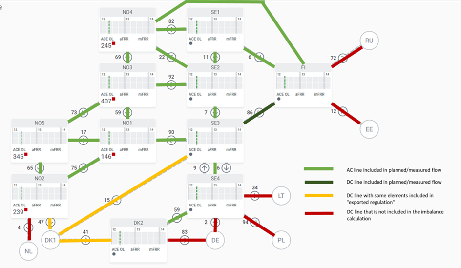
The planned and measured flow shall be calculated for interconnectors within the synchronous system(s). "Exchanged regulation" is calculated for DC-lines within the Nordic balancing market area. See also the figure below.
Information on flows shall be exchanged for all interconnectors, both within and out of our areas.
The map does not include the HVDC to Kriegers Flak or the special case of Bornholm.
In previously NBM work of implementing the ACE OL, we agreed on a definition for ACE OL.
In this specification we did not include all details. We have selected the ENTSO-E’s detailed definition as a source for how to calculate and it contains detailed specification of what is expected to be a positive value and other details ACE OL should contain.
From Article 17.1.h.
| Specification of calculation - ACE OL | |
|---|---|
The error D = MV - (SV + AR) + BEx |
|
Definitions |
Additional Notes |
D = imbalance volume |
|
MV = sum of measured flows over all interconnectors |
|
SV = sum of scheduled flows over all interconnectors. It should include all planned exchanges, hence also balancing energy exchanges. HVDC ramping should not be included. |
|
AR = activated reserves within a control area/block. Calculation of AR may be based upon volumes requested for activation by TSO when metered volumes, as actually delivered by the BSP(s), are not known to the TSO by the submission deadline. |
|
AR = RR + mFRR + aFRR + IN - kΔf |
|
BEx = TSO-TSO energy exchange due to balancing and/or other purposes (e.g. emergency energy delivery, redispatching) |
|
IN = Imbalance Netting |
|
kΔf = frequency bias factor * frequency deviation = estimated FCR activation |
|
AR>0 means net up regulation |
|
AR<0 means net down regulation |
|
D>0 means surplus |
|
D<0 means deficit |
|
MV>0, SV>0 means export direction |
|
MV<0, SV<0 means import direction |
|
BEx>0 means that TSO has a surplus of balancing energy compared to its local needs |
|
BEx<0 means that TSO has a deficit of balancing energy compared to its local needs |
|
With reference to GL EB article 54.6, deficit is equivalent to negative imbalance while excess is equivalent to positive imbalance.
Note: By default data shall be published by imbalance area, which in the majority of cases coincide with scheduling area. Imbalance area may differ from scheduling area as foreseen under EB GL article 54.2
Requirements
Measured flow
For Planned flow, Nordic Communication Infrastructure will provide messages for the following values to FiftyONE.
| Req. | Attribute | Sending frequency | Resolution | Period | Comments |
|---|---|---|---|---|---|
F-BR-1 |
Measured flow |
10 sec |
PT10S |
Max 3h |
Need to clarify how to calculate measured flow; Reference side of corridor. Must provide complete series of data, have historical data. Must include quality attribute. FuTm[1]: Periodic: 10 sec. Value no older than 10 sec, received at least each 10 sec for 98% of time for each QH. |
Measured Flow Historic |
each 3 mnutes, long term 2 hours?? |
10 sec |
Transfer patterns as ACE OL? |
[1] FuTm: Follow up Target model
[2] Req.number is incorrect. See BRS for Flow.